Introduction
The concept of phase permeates seismic data processing and signal processing in general, but it can be awkward to understand, and manipulating it directly can lead to surprising results. It doesn’t help that the word phase is used to mean a variety of things, depending on whether we refer to the propagating wavelet, the observed wavelet, post-stack seismic attributes, or an entire seismic data set. Several publications have discussed the concepts and ambiguities (e.g., Roden and Sepúlveda, 1999; Liner, 2002; Simm and White, 2002).
In this tutorial, we will focus on aspects of phase relevant to the interpreter. We will look at how to manipulate the phase of a seismic trace by manipulating the phase of its Fourier transform and will use that idea to generate the well-known instantaneous phase post-stack attribute. We will also check how close to zero phase our test data set is.
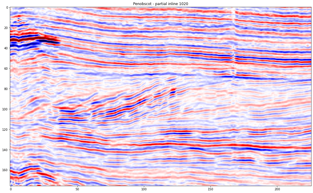
The plots included in this tutorial were created using standard python libraries and the code to reproduce them is available on iooxa here and on the SEG tutorials GitHub repo.
The data we are using are the Penobscot 3D survey from the Open Seismic Repository (https://opendtect.org/osr/), which is openly licensed CC-BY-SA by the Canada Nova Scotia Offshore Petroleum Board, and dGB Earth Sciences.

The Hilbert Transform
The Fourier transform is complex. Taking the transform of any real signal will result in a set of complex coefficients. Complex numbers are essentially 2D vectors, meaning they have two components: magnitude and phase angle. Most of the time when dealing with Fourier transforms, we concentrate on magnitude, which tells us about the distribution of signal energy through frequency. However, every signal also has a phase spectrum, and the phase encodes the signal’s structure — the distribution of the signal energy through time. We do not often examine phase spectrum because it is difficult to interpret, but we can manipulate Fourier phase to change the structure of our signal without affecting its amplitude spectrum.
The Hilbert transform is a linear operator that produces a 90˚ phase shift in a signal, and it is a good first step in our exploration of phase. It is also commonly used in post-stack seismic analysis to generate the analytic signal from which we can compute the standard complex trace attributes such as envelope, instantaneous phase, and instantaneous frequency
The definition of the Hilbert transform is rather cryptic; it is much easier to consider in terms of its Fourier transform definition. The Hilbert transform of a signal is related to the Fourier transform like this:
where:
So we apply a Hilbert transform by multiplying all negative frequencies by and all positive frequencies by , leaving any DC component untouched. This is perhaps not intuitive, but we can gain some additional insight by thinking about it geometrically.
The multiplication of two complex numbers (such as a Fourier coefficient) and (such as above) can be thought of as a rotation in the complex plane. Euler’s formula helps us to see that to rotate any complex number by a specific angle a, we must multiply it by the complex number .
We see that multiplication by alone, as in the equation above, is equivalent to a rotation by 90°. When we take the inverse Fourier transform, the result is a phase-shifted version of our signal.
So, we can generalize the definition of the Hilbert above to produce a phase shift to any angle, :